Construction
Short Assembly Video

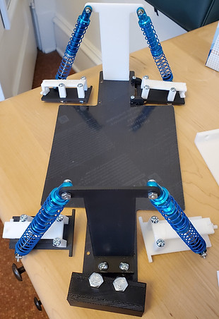
The Completed Chassis Assembly

Initial Assembly of the Suspension Arm

Finished Car

All Assemblies Before Chassis Plate was Cut
Methods, Manufacturing, and Construction
Methods of Design
The biggest problem was making sure that every component would be able to withstand the force from the drop test. To overcome this, statics and strength of materials were applied to many components. The most used equation was the bending stress equation. This was because the maximum stress is when the material will break and therefore the factor that controls the size of the parts. This equation was used many times to optimize the parts by calculating the minimum size of a component, making it lighter. For most of the calculations one or two dimensions were dictated by the geometry of other parts, one example being the suspension tower, which had to fit between the suspension arm fasteners so the shocks would align properly. Then the final dimension, usually thickness, would be dictated by the calculations. This method allowed the parts to be large enough to serve their purpose and be strong, while keeping lightness at the forefront. This focus on lightness was important so the car would perform well during the sprint. The benchmark car chosen in section 2c had a steel chassis, so it can withstand higher stresses generated by greater loads from heavy components or the shock of an impact. However, the acrylic chassis of the project car is lighter, therefore allowing it to perform better in the sprint portion of the ASME RC Baja competition.
Manufacturing
Nearly all parts were 3d printed, because parts with visible defects could be easily reprinted and the process could be closely monitored. The only custom part that could not be 3d printed was the chassis plate because it was about an inch too long to fit in the largest 3d printer the team had access to. So the team decided to laser cut the chassis plate out of ABS which ended up being acrylic as ABS is not compatible with the laser cutting process. The reproducibility of parts was extremely important for this project as many parts needed to be changed based on purchased part dimensions or updates to the drivetrain assembly that were unavailable during the initial design process in the fall. Even though a preliminary design was finished by the end of fall quarter, the chassis and drivetrain assemblies did not match up well, indicating some redesigning would be necessary during the construction process in the winter. Between issues with the drivetrain and poor design choices discovered after manufacturing, five new parts were added, and every part designed in the fall had to be updated. To avoid schedule issues caused by new and redesigned parts, all parts were printed from the fall quarter designs by the third week of winter quarter and the team agreed to finish all part modifications by week eight to leave a week and a half for assembly.
Construction
Nearly all parts were 3d printed, because parts with visible defects could be easily reprinted and the process could be closely monitored. The only custom part that could not be 3d printed was the chassis plate because it was about an inch too long to fit in the largest 3d printer the team had access to. So the team decided to laser cut the chassis plate out of ABS which ended up being acrylic as ABS is not compatible with the laser cutting process. The reproducibility of parts was extremely important for this project as many parts needed to be changed based on purchased part dimensions or updates to the drivetrain assembly that were unavailable during the initial design process in the fall. Even though a preliminary design was finished by the end of fall quarter, the chassis and drivetrain assemblies did not match up well, indicating some redesigning would be necessary during the construction process in the winter. Between issues with the drivetrain and poor design choices discovered after manufacturing, five new parts were added, and every part designed in the fall had to be updated. To avoid schedule issues caused by new and redesigned parts, all parts were printed from the fall quarter designs by the third week of winter quarter and the team agreed to finish all part modifications by week eight to leave a week and a half for assembly.
Both laser cutting and 3d printing have drawbacks. Laser cutting is a subtractive process so more material must be purchased than will be used for the final part, and laser cutters only work on certain materials like acrylic. 3d printing can be a long process and the parts can have rafting that is hard to remove and print errors like lifting from the print platform or uneven texture are not uncommon. However, most of the support material/rafting could be removed with a putty knife, small screwdriver, and occasionally a disk sander. Parts with uneven texture or lifted edges were reprinted to correct the dimensions. To triple check the size of the chassis plate two prototypes were laser cut before the final part was even started.
The assembly was first divided into the drivetrain subassembly and the chassis subassembly. The chassis subassembly was based around the chassis plate with the suspension tower, suspension arm subassemblies, bottom cover, and front bumper attached to it. The suspension arm subassemblies were based around the suspension arm with the suspension arm fastener connecting the arm to the chassis, the steering block mounting on the arm and attaching to the axel and the wheel. The steering block or back axle supports were also held in place with the steering block support above the block. The shocks attach to the suspension tower and the suspension arm.