Analysis
The analysis of the chassis and suspension components includes statics, dynamics, and strength of materials all focused on different loads and stresses the suspension and chassis underwent. Strength of the materials used for this project is key and analysis of frontal and wheel impacts determined the specs of the front bumper and the strength of the suspension. Flexure analysis of a flat plate determined the thickness of the chassis plate. The requirements specify the chassis must support the drivetrain components (weighing up to five lbs.) without bending. Flexure analysis was performed and the plate was determined to be a minimum of 0.024 inches The nearest standard size for sheet ABS is 1/8 inch, so size was used. The thickness of the front bumper in front of the chassis plate was also determined through analysis. The maximum speed of 30 mph given by the designer of the drivetrain was used in the conservation of energy equation. Work energy was then used to find the thickness of material needed which was 0.2 inches. This calculation helped to optimize the design by making the bumper as small as possible while still protecting the car.
Design Requirements
-
The chassis must weigh less than four pounds.
-
This vehicle must be able to withstand a two foot drop.
-
The suspension must have one and a half inches of free movement.
-
The chassis must support drivetrain components up to five pounds without bending.
-
The car must sustain a frontal impact of thirty miles per hour without breaking.
-
The car must turn within a three foot radius.
Design Requirements and Analyses
Many of the analyses shown in the report (available on the home page) were performed to determine component thickness using the forces generated by the drop test and the basic stress equation to meet the second requirement. The first requirement doesn't have an associated analysis because the components were all assumed to be light and weight was monitored through solidworks. For the third requirement, analyses like the one above were performed to determine the required dimensions of a shock sprint that would absorb the impact from the drop test and be the length from the requirements. A plate bending equation from Mark's Handbook was used was used to determine the necessary plate thickness to achieve the fourth requirement. The forces generated by the test for the fifth requirement generally only strongly impact the front bumper. To ensure success for the final requirement, the front bumper was treated as a spring and analyzed with Hooke's law to determine proper material thickness. Each analysis is detailed below.
ii. Analysis 2: Front Bumper as a Spring
The maximum top speed of the car is 30 mph which would cause significant damage to the car if it were to run into a wall at top speed. This calculation determined the required thickness of a bumper using conservation of energy. The bumper was assumed to be made of ninjaflex with a width of three inches and a height of one inch and to act as a spring. The tensile modulus from the material spec sheet was used to find the approximate k factor of the material. The k factor was used to determine the force that the bumper could absorb. Then conservation of energy was applied, and it was determined that a 0.6 inch thick bumper could absorb the impact.

iv. Analysis 4: Stiffness of Shocks
This analysis took the force determined in analysis three and used Hooke’s law to determine the spring constant necessary to absorb a 27 pound force applied to each wheel. The result of this analysis was used to determine the necessary coil diameter for each shock.

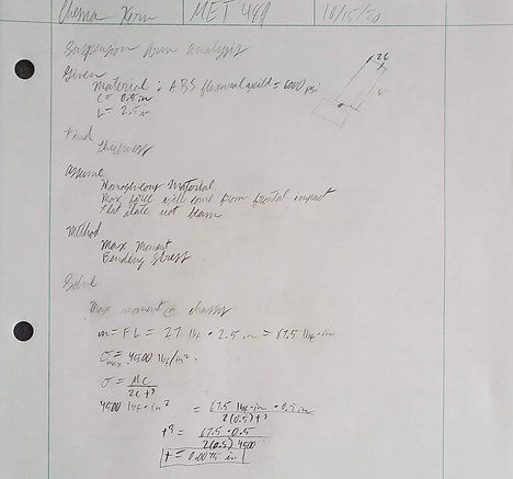
vi. Analysis 6: Suspension Arm in Bending
Analysis three determined the drop force on each wheel to be 27 pounds of force. Analysis five used this information to determine the necessary thickness of a suspension arm made from ABS. The length of the suspension arm was determined to be 2.5 inches because a shorter length would have the chassis interfere with the wheels. The maximum bending stress of the suspension arm was assumed to be equal to the flexural yield strength of ABS found on Matweb. The bending stress equation was then applied to find the minimum thickness of the suspension arm to equal 0.0075 inches.

viii. Analysis 8: Suspension Tower Thickness
Analysis eight used beam bending to determine the necessary thickness of the suspension tower. The force (assumed to be equal to drop force from analysis three) was assumed to only act on the top flanges of the tower. For this reason, the flange was analyzed as a beam. First, the reactions on the tower side were determined using statics and represented on a free body diagram. Then maximum moment was determined by drawing shear and moment diagrams. From there, minimum thickness was determined to be 0.0094 inches from the stress equation.

x. Analysis 10: Shear in Suspension Arm
Once again the drop force from analysis three was used to determine the necessary thickness of the flange of the suspension tower. First a free body diagram was used to determine the location of the forces, then a shear diagram was used to determine maximum shear, and a moment diagram was used to determine the maximum moment. Finally, the stress equation was used to determine the minimum thickness to be 0.133 inches, which was rounded up to 0.2 inches to simplify dimensions.

xii. Analysis 12: Pin Size for Front Bumper
This analysis used shear stress to determine the minimum diameter for the pins used to hold the front bumper to the chassis plate. The yield stress of steel was determined to be 36000 psi from Hibbler’s statics. The force acting on the pins was assumed to be equal to the impact force found in analysis two. Then the equation was used to determine the area to be 0.075 inches. Finally, the area was used to determine the diameter of the pins to be 0.309 inches.
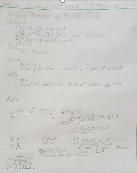
Analysis 1: Chassis Plate in Bending
Flat plate analysis was applied to the chassis plate to determine the thickness needed. The maximum weight of the drivetrain components mounted to the chassis plate was 5 lbs. To have a factor of safety of 1.5, the chassis plate was designed to support 7.5 lbs. The calculations shown in appendix A-1 determine the necessary thickness of the chassis plate through bending analysis of a flat rectangular plate. The calculations indicate that a thickness 0.024 inches is required.

iii. Analysis 3: Drop Force on Shocks
The requirements specify that the car must survive a two foot drop when landing directly on its wheels. These calculations determined the force the car experiences as a result of the drop as well as the force to be absorbed by each shock using conservation of energy and the work equation. The calculations show a force of 27 pounds exerted on each wheel, assuming symmetrical loading.

v. Analysis 5: Required Diameter of Shock Springs
This analysis took the spring constant determined in analysis three and used in the equation K=(Gd^4)/(8nD^3) where K is the spring constant, d is the estimated diameter of the wire that makes up the spring, n is the number of coils, and D is the diameter of the coils. Assuming that the spring is made from steel, is three inches long, and has 18 coils, the minimum spring diameter comes out to be 0.034 inches. All assumptions were based on a shock from a previous year found in the senior project room.
vii. Analysis 7: Suspension Arm Pin Size
This analysis determined the necessary diameter of the pin section of the suspension arm using shear stress. A safety factor of 1.5 was applied to the max shear force of ABS (Matweb) making the design stress 1000 psi. The diameter was then found from the equation T=F/2Tdes. Force was taken to be the drop force per wheel from analysis three and was divided by two because the force is divided between two pins on either side of the arm. The minimum diameter was found to be 0.13 inches.

xi. Analysis 9: Suspension Tower Flange Thickness
Once again the drop force from analysis three was used to determine the necessary thickness of the flange of the suspension tower. First a free body diagram was used to determine the location of the forces, then a shear diagram was used to determine maximum shear, and a moment diagram was used to determine the maximum moment. Finally, the stress equation was used to determine the minimum thickness to be 0.133 inches, which was rounded up to 0.2 inches to simplify dimensions.

xi. Analysis 11: Suspension Arm Fastener in Bending
The ABS suspension fasteners were predicted to carry the largest stress in the round hole, so this analysis determined the thickness of material surrounding the hole. Using the equation and taking the force to be the drop force from analysis three, the thickness was determined to be 0.00675 inches.
